Contents
- 1 Introduction to HDMI Technology
- 2 Essential Components of an HDMI Cable
- 3 Interpreting the HDMI Pinout Configuration
- 4 Step-by-Step Guide
- 5 Common HDMI Wiring Issues and Solutions
- 6 Best Practices for Wiring HDMI Connectors
- 7
- 8 Tips for DIY HDMI Cable Repairs and Customization
- 9 The Future of HDMI and Evolving Standards
- 10 Conclusion: Mastering the HDMI Wiring Diagram
Introduction to HDMI Technology
HDMI, short for High-Definition Multimedia Interface, is a vital technology in today’s digital media. This widely-used interface delivers both high-definition video and audio through a single cable. Most modern TVs, gaming consoles, computers, and other entertainment devices depend on HDMI for quality output. Understanding the HDMI wiring diagram is key when installing or troubleshooting devices. The wiring diagram shows how signals travel between devices via HDMI cables. There are 19 pins in a standard HDMI connector, each with a specific function. They work together to transfer data seamlessly.
HDMI technology has evolved over the years. It offers several versions, each with improvements in speed, resolution, and audio quality. For example, the latest HDMI 2.1 supports up to 10K resolution with enhanced audio return channels. As a blogger passionate about technology, having a grasp on HDMI’s capabilities ensures you can guide your readers through any issues or upgrades.
Essential Components of an HDMI Cable
When tackling an HDMI wiring diagram, you must first understand the cable’s essential components.
Outer Jacket: This is the cable’s protective covering. It guards against physical damage.
Shielding: Beneath the jacket, shielding reduces interference from external signals. It ensures the purity of signal.
Insulation: Surrounding each wire, insulation prevents cross-talk between the wires inside the HDMI cable.
Twisted pairs: HDMI cables have twisted pairs of wires for video and audio signals. This design minimizes interference.
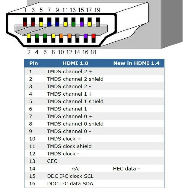
Connector: The end of the HDMI cable has a connector with 19 pins. Each pin has its function in the wiring diagram.
The TMDS channels: These are vital for transferring video and audio data. HDMI has three TMDS channels.
Each part of the HDMI cable plays a role in keeping the signal strong and clear. When you understand these components, reading an HDMI wiring diagram becomes easier. This knowledge helps with installation and troubleshooting tasks.
Interpreting the HDMI Pinout Configuration
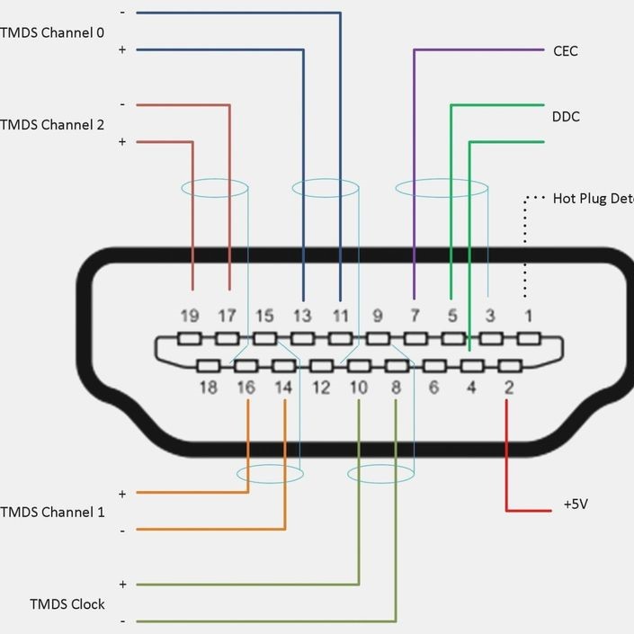
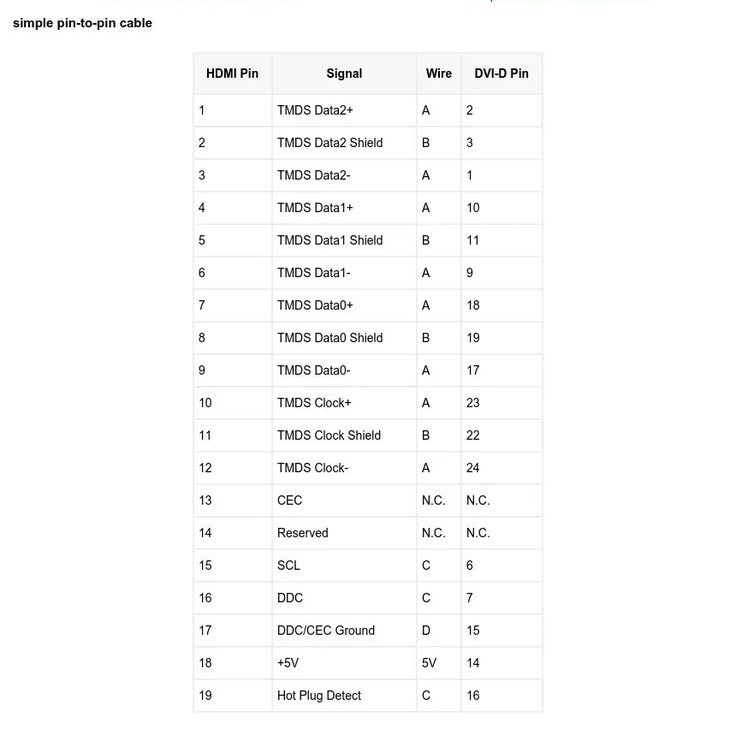
Interpreting the HDMI pinout is crucial for any DIY enthusiast or technician. The pinout configuration refers to the purpose of each of the 19 pins found in a standard HDMI connector. Knowing the function of each pin can help you understand how HDMI transmits high-quality video and audio.
The pinout configuration includes:
- Power and grounding pins: These provide power to the HDMI interface and grounding for the electrical circuits.
- TMDS data channels: There are three of these, each responsible for transmitting a portion of the video and audio data.
- TMDS clock channel: This pin helps synchronize the data that’s transmitted over the TMDS data channels.
- The CEC (Consumer Electronics Control) pin: It allows users to control multiple HDMI-connected devices with one remote.
- The ARC (Audio Return Channel) pin: This is used to send audio from a TV back to an A/V receiver or soundbar.
- HEC (HDMI Ethernet Channel) and DDC (Display Data Channel) pins: They provide internet connectivity and enable communication between devices for resolutions, screen size, and formats.
- Hot Plug Detect (HPD) pin: Detects when an HDMI connection has been made or removed.
By knowing these functions, you can troubleshoot problems more effectively. If a pin is damaged or malfunctioning, it might affect a specific part of the HDMI service like audio output or screen resolution. Professionals use the HDMI wiring diagram to match each pin with its corresponding cable wire when repairing or creating custom HDMI solutions. Armed with this understanding, the HDMI wiring diagram becomes a map to the successful interconnection of your digital media devices.
Step-by-Step Guide
To effectively read HDMI wiring diagrams, follow these clear steps:
- Identify the Connector Type: Start by looking at the shape and size of the connector. Make sure it is a standard 19-pin HDMI connector.
- Examine the Pin Numbers: Locate the tiny numbers next to each pin in the diagram. They correspond to the specific functions previously discussed.
- Understand the Color Coding: Wiring diagrams often use colors to differentiate wires. Match the colors on the diagram with the actual wires.
- Analyze Signal Directions: Arrows or labels on the diagram show the direction of the signal. This helps in understanding how data flows through the cable.
- Check for TMDS Channels: Locate the three TMDS channels necessary for video and audio transmission. Pin numbers 1 to 9 are usually dedicated to these channels.
- Confirm Power and Grounding Pins: Power is typically supplied through pin 18 while grounding is achieved via pin 17.
- Review Additional Features: Pins for CEC and ARC might be highlighted. Pin 13 is for CEC and pin 14 for ARC functionality.
- Spot the HPD Pin: The Hot Plug Detect pin is crucial for signal recognition. It’s usually pin 19.
By closely following these steps, you’ll be more confident in your understanding of HDMI wiring diagrams. With practice, you’ll navigate the complexities of HDMI connectivity like a pro.
Common HDMI Wiring Issues and Solutions
When working with HDMI technology, you might encounter common wiring issues. Solving these effectively is crucial for a seamless user experience. Here are some frequent problems and their resolutions:
Signal Loss or Degradation
- Understanding the Problem: Signal loss or degradation occurs when a video or audio signal weakens, often due to long cable lengths or the use of low-quality cables. This can lead to blurry images or unstable audio during transmission.
- Common Causes: Longer HDMI cables can cause electromagnetic interference and increase resistance, impacting the signal quality. Additionally, inferior cables may lack the shielding necessary to maintain signal integrity over distance.
- Proposed Solution: To mitigate this issue, consider using a shorter HDMI cable to reduce distance-related degradation. If a longer cable is necessary, investing in a high-quality, well-shielded cable or employing a signal booster can significantly improve performance.
Physical Damage to Cables
- Identifying Damage: Physical damage to cables, such as exposed or frayed wires, can substantially disrupt signal transmission. This can lead to a total loss of signal or intermittent connectivity.
- Impact of Damage: Damaged cables may create electrical shorts or signal interruptions, resulting in poor video/image quality or complete black screens. Recognizing the signs of damage early can save additional troubleshooting later.
- Proposed Solution: The best course of action is to replace any damaged cables with new ones. Ensure that you use high-quality cables that are appropriate for your devices and intended use.
Loose Connections
- Symptoms of Loose Connections: If the connector at either end of the cable is not firmly plugged in, the signal can be interrupted. This may result in flickering images or complete signal loss.
- Consequences of Loose Connections: Loose connections not only lead to inconsistent signals but can also cause wear on connectors over time, leading to further connectivity issues.
- Proposed Solution: To resolve this problem, ensure that each connector is tightly and securely attached to the corresponding device. Regularly check connections, especially after moving devices or cables.
Compatibility Problems
- Identifying Compatibility Issues: Some devices may have compatibility problems with specific versions of HDMI. For example, an old TV may not support the advanced features available on newer HDMI versions.
- Signs of Incompatibility: Both devices may connect, but certain features like 4K video or audio formats may not function correctly, leading to data loss in the transmission. Understanding HDMI version differences is critical.
- Proposed Solution: Before attempting to connect devices, verify that both the source and display support the same HDMI version. Reference the product manuals or manufacturer websites to ensure compatibility.
Audio Issues
- Common Audio Problems: Audio issues such as no sound or poor audio quality are frequent complaints among users. This can stem from incorrect settings or physical connection issues.
- Identifying the Root Cause: Problems might arise due to incorrect audio settings on the source device or an improper connection on the Audio Return Channel (ARC) pin.
- Proposed Solution: First, check the ARC pin connection to ensure it is properly configured. Then, inspect and adjust the audio settings on your device. Confirm that the correct audio output is selected.
No Video Signal
- Understanding Signal Loss: If there is a complete loss of picture, the issue may relate specifically to the TMDS (Transition Minimized Differential Signaling) channels within the HDMI cable.
- Symptoms to Watch For: Signs of no video signal may include a blank screen or error messages stating “no signal” on the receiving device.
- Proposed Solution: Start by inspecting the HDMI cable for physical damage and ensuring all pins are connected properly within the connectors. Replacing the cable may also be necessary if the problem persists.
Interference from Other Devices
- Recognizing Interference Sources: Electromagnetic interference can seriously affect signal quality and transmission. Devices like microwaves, cordless phones, or poorly shielded cables can introduce noise into the signal pathway.
- Consequences of Interference: This interference can distort audio and visual signals, leading to disruptions during playback or live events. Identifying sources of interference is critical to resolving issues.
- Proposed Solution: To counteract these issues, use HDMI cables with better shielding to minimize exposure to interference. Additionally, reposition the cable away from potential sources of electromagnetic interference to enhance signal clarity and stability.
By addressing these HDMI wiring issues properly, you can maintain a high-quality audiovisual experience. Keep this troubleshooting guide handy to overcome any HDMI challenges you may face.
Best Practices for Wiring HDMI Connectors
When you’re setting up or repairing HDMI connections, certain best practices can help ensure a reliable setup. By following these tips, your HDMI connections will consistently provide high-quality audio and video.
- Use the Right Cable: Always choose a high-quality HDMI cable suitable for your device’s HDMI version.
- Ensure a Secure Fit: Confirm that connectors fit snugly in the device ports to prevent signal loss.
- Avoid Bending Cables Sharply: Sharp bends can damage the internal wiring, leading to signal issues.
- Keep Cable Length Appropriate: Shorter HDMI cables tend to perform better, so use the shortest cable necessary for your setup.
- Label Cables and Ports: If managing multiple connections, label each cable and port to avoid confusion.
- Check for Dust and Debris: Clean your connectors and ports before connecting to minimize connectivity problems.
- Regularly Inspect for Wear: Look for signs of damage on the cables and connectors and replace them if necessary.
- Disconnect Carefully: When removing HDMI cables, pull gently on the connector, not the cable, to avoid damage.
Adhering to these practices not only prevents common issues but also extends the lifespan of your HDMI cables and devices. Remember, a little attention to detail goes a long way in achieving the best possible audiovisual experience.
Tips for DIY HDMI Cable Repairs and Customization
Embarking on DIY HDMI cable repairs and customization can be daunting. Still, it’s an empowering way to manage your own tech needs. Here’s how you can do it right.
Start by gathering the right tools: a suitable wire stripper, soldering iron, and a multimeter. Quality tools make the job easier and safer. Next, study the HDMI wiring diagram carefully to know where each wire goes. Pay close attention to the pinout configuration. It’s the roadmap for your repairs and customizations.
For repairs, first diagnose the issue with your HDMI cable. Use a multimeter to check for continuity. This will help you find where the connection is broken. If there’s an issue at the connector, you might need to re-solder the wires to the pins. Make sure you match the colors correctly to the pin functions.
For customizations, like creating a cable of a specific length, cut the outer jacket and shielding with precision. Avoid damaging the twisted pairs. Strip the necessary length and tin the tips before soldering them to the pins. It’s delicate work, but patience pays off.
Remember to test your DIY repairs or custom cable with your devices before finalizing everything. You want to ensure that your video and audio work flawlessly. Lastly, protect your handiwork with heat-shrink tubing or electrical tape, securing a professional finish.
These steps, combined with a careful approach, make DIY HDMI cable repairs and customization a rewarding task. With the right prep and attention to detail, you can keep your HDMI-equipped devices connected and functioning perfectly.
The Future of HDMI and Evolving Standards
As HDMI technology continues to advance, new standards emerge to meet the evolving demands of digital media. The future of HDMI holds exciting prospects with enhancements in speed, resolution, and overall performance. The introduction of HDMI 2.1 has already set the stage for significant improvements, supporting resolutions up to 10K and featuring higher bandwidth capabilities. With such advancements, the HDMI wiring diagram will also evolve, adapting to changes in pin configuration and signal transmission methods.
In the near future, we can anticipate HDMI standards that further reduce latency and improve refresh rates. This is crucial for gaming and virtual reality applications, where split-second timing affects the user experience. Additionally, the trend towards even higher resolutions and immersive audio formats means that HDMI cables and connectors must evolve to handle more complex wiring diagrams and increased data transfer rates.
Manufacturers are also working on enhancing HDMI’s convenience features, like eARC (Enhanced Audio Return Channel), allowing for more sophisticated audio system setups without additional cables. Furthermore, HDMI might see improvements in its CEC capabilities to streamline device control across an even wider range of devices.
It’s important for professionals and DIY aficionados to stay informed about these changes. The ability to interpret updated HDMI wiring diagrams will remain a vital skill as new HDMI standards come into play. By keeping up with these advancements, you can ensure that your expertise in HDMI technology remains current, providing you with the know-how to manage cutting-edge audiovisual setups with confidence.
Conclusion: Mastering the HDMI Wiring Diagram
In summary, cracking the HDMI wiring diagram code is critical for anyone looking to build and maintain a high-quality audio and video setup. Understanding the wiring configuration, common issues, and practical tips allows users to optimize their connections for better performance.
By monitoring your HDMI connections and staying informed on technology trends, you can enhance your multimedia experience significantly. Whether you’re troubleshooting or expanding your setup, a solid grasp of HDMI wiring concepts will pay off in the long run, ensuring you enjoy seamless audio and video playback for years to come.